Product Description
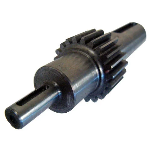
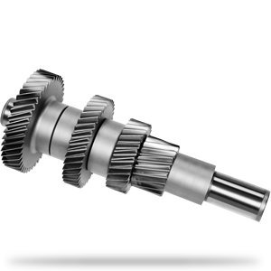
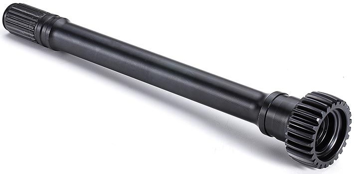
high precision custommized helical gear shaft drive shaft reducer Gear Shaft
Product Description
Hyton provides one-stop solution service for your metallurgical equipment spare parts, currently we produce rolling mill rolls, guide, blades, gears, sprocket wheels, worm, worm gears, flange processing parts, welding processing parts and etc.Gear rack is a rotating machine part with cut teeth, or cogs, which mesh with another toothed part in order to transmit torque. It includes spur gear, helical gear, skew gear, bevel gear, spiral bevel gear and so on. It is widely used for all kinds of machinery equipment.
| Product Name | Gear Racks |
| Material | C45, 40Cr, 20CrMnTi, 42CrMo, Copper, Stainless steel |
| Tolerance | 0.001mm – 0.01mm – 0.1mm |
| Tooth Hardness | 50-60 HRC |
| Length | Customized |
| Processing | Forging, Machining, Hobbing, Milling, Shaving, Grinding, Heat treatment |
| Inspection | Material Report, Dimensions Checking Report, Hardness Report |
| Payment | L/C, Western Union, D/P, D/A, T/T, MoneyGram |
| Lead Time | 4 weeks |
Company Profile
HangZhou CHINAMFG Heavy Industry Technology Development Co., Ltd. is a leading enterprise in the wear-resistant casting of large engineering machinery and the forging of large equipment parts located in the New Material Industrial Park, Xihu (West Lake) Dis. High-Tech Zone, HangZhou City, the company covers an area of 90 Square kilometer and currently has more than 300 employees. The company is equipped with lost molding production line and lost casting production line imported from FATA Company in Italy, Inductotherm Vacuum Degassing Furnace(USA), Foseco Casting Technology(U.K), SPECTRO Spectrometer (Germany), the currently most advanced ZZ418A vertical parting flaskless shoot squeeze molding machine Disa production line, horizontal molding line and self-control lost casting production line in China, the most advanced sand treatment system in China. With 3 gas trolley heat treatment CHINAMFG and pusher-type CHINAMFG full-automatic heat treatment production lines, the company can annually produce 30,000 tons of various wear-resisting castings and metallurgical equipment forging parts.
Manufacturing Technique
Inspection
Dimension Measurement
According to the product drawings provided by customers, we will conduct strict dimensional inspection before the products are shipped.
Hardness TestAccording to the drawing requirements provided by customers, we will conduct hardness inspection before the products are shipped.
Roughness MeasurementAccording to the drawing requirements provided by customers, we will conduct roughness inspection before the products are shipped.
Packing and Shipping
To better ensure the safety of your goods, professional, environmentally friendly, convenient and efficient packaging services will be provided. After goods well packaged, we need only 1 day ship goods to ZheJiang port, which means that most of the spare parts you bought from Hyton, it will get your port within 45 days all around the world if shipment by sea.
Our Advantages
1)Your inquiry related to our product & price will be rapidly.
2) Well trained & experienced staff are to answer all your inquiries in English of course.
3) Your business relationship with us will be confidential to any third party.
4) One stop purchase service: extensive rang of products for qualified offering.
5) We response to client’s inquiry within 12 hours.
FAQ
1.Q: What kind of products do you make?
A: We specialize in metallurgical equipment casting and forging parts, such as forging rolls, guide, blades, gears, sprocket wheels, worm, worm gears, flange processing parts, welding processing parts and etc.
2.Q: What kind of material do you offer?
A: High manganese steel, high chrome iron, alloy steel, low carbon steel, medium carbon steel, Stainless Steel and etc.
3.Q: What is your time of delivery?
A: Our lead time is generally 2-4 weeks for casting parts and shipping time is about 2-4 weeks.
4.Q: How to test your quality?
A: We will show you material inspection and measurement inspection after fininsh the goods, at the same time, we will give you the life time guarantee letter after shipping the goods. The best suggestion to all the customer who may interest our product-Test 2 set first, all the good business relationship all from test and trust.
| Hardness: | Hardened Tooth Surface |
|---|---|
| Gear Position: | External Gear |
| Manufacturing Method: | Cast Gear |
| Toothed Portion Shape: | Spur Gear |
| Material: | Stainless Steel |
| Type: | Circular Gear |
| Customization: |
Available
| Customized Request |
|---|
Can you explain the impact of gear shaft misalignment on gear performance?
Gear shaft misalignment can have a significant impact on the performance of gears within a system. When gear shafts are not properly aligned, several issues can arise, affecting the overall functionality and reliability of the gears. Let’s explore the impact of gear shaft misalignment in detail:
- Reduced Efficiency:
Misalignment causes a loss of efficiency in gear systems. When gear shafts are misaligned, the teeth of the gears do not mesh correctly, leading to increased friction and energy losses. This results in reduced power transmission efficiency, as a portion of the input power is dissipated as heat instead of being effectively transferred through the gears.
- Increased Wear and Fatigue:
Misalignment can lead to uneven contact and loading between gear teeth. This uneven distribution of forces causes localized high-stress areas on the gear teeth, leading to accelerated wear and fatigue. The concentrated stress on specific areas of the teeth can result in pitting, wear, and even tooth breakage over time. Increased wear and fatigue significantly reduce the lifespan of gears and can lead to unexpected failures.
- Noise and Vibration:
Gear shaft misalignment often results in increased noise and vibration levels within the gear system. As the misaligned teeth engage, they generate excessive noise due to impact and increased friction. The vibrations caused by the misalignment can propagate through the gear assembly and the surrounding components, causing additional noise and potentially affecting the performance and lifespan of the entire system.
- Loss of Tooth Contact:
Misalignment can cause a loss of proper tooth contact between the gears. Insufficient tooth contact reduces the load-carrying capacity of the gears and compromises the transmission of torque. The reduced contact area also increases the likelihood of localized stress concentrations, leading to premature wear and failure.
- Overloading and Unbalanced Loads:
Gear shaft misalignment can result in overloading and unbalanced loads on the gears. Misalignment can cause uneven distribution of forces, with some teeth bearing a higher load than others. This can lead to excessive stress on specific gear teeth, potentially exceeding their load-carrying capacity. Over time, the overloading of certain teeth can result in accelerated wear, tooth breakage, and even catastrophic gear failure.
- Seal and Bearing Issues:
Misalignment can also affect the performance of seals and bearings within the gear system. Misaligned gear shafts can create additional radial or axial loads on the bearings, reducing their lifespan and causing premature failure. Seal integrity can also be compromised, leading to leaks and contamination of the gear system, further exacerbating the issues associated with misalignment.
In summary, gear shaft misalignment has a detrimental impact on gear performance. It reduces efficiency, increases wear and fatigue, generates noise and vibration, causes loss of tooth contact, leads to overloading and unbalanced loads, and affects the performance of seals and bearings. Proper alignment of gear shafts is crucial to ensure optimal gear performance, longevity, and reliable power transmission within the gear system.
What are the factors to consider when designing gear shafts for specific applications?
Designing gear shafts for specific applications requires careful consideration of various factors to ensure optimal performance and reliability. Let’s explore the key factors that should be taken into account during the design process:
- Load and Torque Requirements:
The load and torque requirements of the specific application are crucial considerations. Understanding the maximum load the gear shaft will experience and the torque it needs to transmit is essential for selecting appropriate materials, determining the required dimensions, and ensuring the gear shaft can handle the anticipated forces effectively.
- Gear Type and Configuration:
The gear type and configuration directly influence the design of the gear shaft. Different gear types, such as spur gears, helical gears, bevel gears, or worm gears, have unique characteristics that impact the design considerations for the gear shaft. Factors such as gear tooth profile, pitch, pressure angle, and gear ratio need to be taken into account during the design process to ensure proper alignment, engagement, and efficient power transmission.
- Material Selection:
Selecting the appropriate material for the gear shaft is crucial for its strength, durability, and performance. Factors such as the required strength, wear resistance, fatigue resistance, and corrosion resistance should be considered when choosing the material. Common materials for gear shafts include various steels, alloys, and sometimes specialized materials like bronze or brass, depending on the specific application requirements.
- Shaft Dimensions and Geometry:
The dimensions and geometry of the gear shaft need to be carefully determined. Factors such as shaft diameter, length, keyways, chamfers, and fillets are important considerations. Proper shaft dimensions and geometry ensure sufficient strength, proper fit within the gear assembly, and compatibility with other components within the system.
- Bearing Support and Lubrication:
The gear shaft design should incorporate provisions for bearing support and lubrication. Bearings placed along the gear shaft help reduce friction, support the shaft under load, and ensure smooth rotation. Adequate lubrication, such as oil or grease, is necessary to minimize wear between the gear shaft and bearings, as well as to reduce heat generation and promote efficient operation.
- Heat Treatment and Surface Finish:
Depending on the application requirements, heat treatment processes like quenching and tempering may be applied to enhance the mechanical properties of the gear shaft. Heat treatment can improve hardness, strength, and toughness, increasing the gear shaft’s ability to withstand high loads and resist wear. Additionally, considering the surface finish of the gear shaft can help reduce friction, improve gear meshing, and minimize the risk of surface damage.
- Manufacturability and Cost:
Designing gear shafts should also take into account manufacturability and cost considerations. The design should be feasible for manufacturing processes such as machining, forging, or casting, depending on the chosen material and complexity of the design. The design should also aim to optimize material usage and minimize manufacturing costs while meeting the required performance criteria.
In summary, when designing gear shafts for specific applications, factors such as load and torque requirements, gear type and configuration, material selection, shaft dimensions and geometry, bearing support and lubrication, heat treatment and surface finish, as well as manufacturability and cost considerations, should all be carefully evaluated. By considering these factors, a well-designed gear shaft can be developed to meet the specific needs of the application, ensuring reliable and efficient power transmission within the gear system.
How do gear shafts differ from other components in gear mechanisms?
Gear shafts have distinct characteristics that differentiate them from other components in gear mechanisms. Here are some key differences between gear shafts and other components:
- Function:
Gear shafts serve as the mechanical linkages that connect and transmit rotational motion between gears. Their primary function is to transfer power and torque from one gear to another, enabling the desired mechanical output. Other components in gear mechanisms, such as gears themselves, may have different functions, such as meshing with other gears, providing different gear ratios, or changing the direction of motion.
- Structure and Design:
Gear shafts typically have a cylindrical or rod-like structure with a smooth surface. They are designed to provide support, alignment, and rotational movement for the connected gears. In contrast, other components, such as gears, may have complex tooth profiles, specific shapes, or specialized features to achieve their intended functions, such as transmitting motion, altering speed, or multiplying torque.
- Location and Mounting:
Gear shafts are often positioned centrally within gear mechanisms and are mounted on bearings or bushings. This central location allows them to connect with multiple gears and efficiently transmit power. Other components, such as gears, may be positioned at different locations within the mechanism, depending on their specific roles and interactions with other gears.
- Rotational Movement:
Gear shafts primarily rotate within the gear mechanism, transmitting the rotational motion from one gear to another. They are designed to withstand the torque and rotational forces applied during operation. In contrast, other components, such as gears, may have different types of movement or interactions, such as meshing with other gears, sliding, or engaging and disengaging with additional mechanisms or clutches.
- Size and Dimension:
Gear shafts can vary in size and dimension depending on the specific application and gear mechanism requirements. They need to be designed to handle the load, torque, and speed demands of the system. Other components, such as gears, may also come in various sizes, but their shape, tooth profiles, and dimensions are tailored to achieve specific gear ratios, rotational speeds, or torque multiplication.
- Material Selection:
Gear shafts are commonly made from strong and durable materials, such as steel or alloy metals, to withstand the forces and stresses encountered during operation. The material selection for gear shafts prioritizes strength, wear resistance, and fatigue resistance. Other components, such as gears, may have different material requirements based on their specific functions, such as hardness, friction properties, or heat dissipation.
In summary, gear shafts differ from other components in gear mechanisms in terms of their function, structure, location, movement, size, and material selection. Gear shafts primarily serve to transmit power and torque between gears, providing support, alignment, and rotational movement. Understanding these differences is crucial for designing and assembling efficient and reliable gear mechanisms.


editor by CX 2023-10-12