Product Description
Product Description
Boqiang Drive F series parallel shaft in-line Helical gear motors Drive Reduction Gear Box replace bevel gear box reduction gear harmonic drive reducer
Technical parameters
| Ratio | 5.36-178.37 |
| Input power | 0.12-200KW |
| Output torque | 10-61900n.M |
| Output speed | 0.08-261rpm |
| Mounting type | Foot mounted, foot mounted with CHINAMFG shaft, output flange mounted, hollow shaft mounted, B5 flange mounted with hollow shaft, foot mounted with hollow shaft, B14 flange mounted with hollow shaft, foot mounted with splined hole, foot mounted with shrink disk, hollow shaft mounted with anti-torque arm. |
| Input Method | Flange input(P or SF), shaft input(AD), inline AC motor input, or AQA servo motor |
| Brake Release | HF-manual release(lock in the brake release position), HR-manual release(autom-atic braking position) |
| Thermistor | TF(Thermistor protection PTC thermisto) TH(Thermistor protection Bimetal swotc |
Specification
|
Model |
Shaft Dia. mm |
Horizontal Center Height mm |
External Flange Dia. mm |
Power |
Ratio (i) |
Nominal Torque (Nm) |
|
|
Solid Shaft |
Hollow Shaft |
||||||
|
F/FF/FA/FAF37 |
ф25 |
ф30 |
76 |
160 |
0.18-3 | 3.81-128.51 | 10-228 |
|
F/FF/FA/FAF47 |
ф30 |
ф35 |
77 |
200 |
0.18-3 | 9.08-189.39 | 126-393 |
|
F/FF/FA/FAF57 |
ф35 |
ф40 |
93 |
250 |
0.18-5.5 | 5.18-127.27 | 129-624 |
|
F/FF/FA/FAF67 |
ф40 |
ф40 |
97 |
250 |
0.18-5.5 | 4.21-228.99 | 105-871 |
|
F/FF/FA/FAF77 |
ф50 |
ф50 |
121 |
300 |
0.18-11 | 4.30-281.71 | 198-1654 |
|
F/FF/FA/FAF87 |
ф60 |
ф60 |
152 |
350 |
0.37-22 | 4.20-271.92 | 387-3018 |
|
F/FF/FA/FAF97 |
ф70 |
ф70 |
178 |
450 |
0.55-30 | 4.68-276.64 | 857-4049 |
|
F/FF/FA/FAF107 |
ф90 |
ф90 |
200 |
450 |
1.1-45 | 6.20-255.25 | 1391-7161 |
|
F/FF/FA/FAF127 |
ф110 |
ф100 |
236 |
550 |
4-90 | 4.63-172.33 | 1545-13426 |
|
F/FF/FA/FAF157 |
ф120 |
ф120 |
286 |
660 |
5.5-200 | 11.92-266.76 | 7900-2 0571 |
F series parallel shaft helical gear reduction motor has the following design:
1.F. Y .. Foot shaft extension installation parallel shaft helical gear reducer:
2.FA.. Y .. The base hollow shaft is provided with a parallel shaft helical gear reducer:
3.FAZ… Y .. The small flange hollow shaft is installed with the parallel shaft helical gear reducer
4.FF..Y .. Flange shaft extension type installation parallel shaft helical gear reducer
5.FAF.. Y .. The flanged hollow shaft is provided with a parallel shaft helical gear reducer
6. F(FA FF FAF FAZ).. P/SF. Connecting flange input type parallel shaft helical gear reducer
7.F(FA FF FAF FAZ).. AD .. Shaft input parallel shaft helical gear reducer
8.FA(FF F FAF FAZ)…R … Y. Combined parallel shaft helical gear reducer
Mounting poKition:
PoKition of the motor thermal box:
Input power rating and permissible torque:
Gear unit weight:
Photos of the factory area
ZHangZhoug Boqiang Transmission Co., Ltd. was established in 2002 and is a high-tech enterprise that integrates design, development, manufacturing, and operation, producing and selling reduction motors and power transmission equipment. The company is located in Oubei Town, HangZhoua County, at the forefront of national reform and opening up, known as the “Little Xihu (West Lake) Dis.” of HangZhou. Close to National Highway 104 and east to HangZhou International Airport and Xihu (West Lake) Dis. International Container Terminal; South to HangZhou Railway Station and Passenger Transport Center; There are also many national tourist attractions such as Yandang Mountain and Xihu (West Lake) Dis. River. With convenient transportation and unique geographical location, it is highly welcomed by domestic and foreign users.
Our company produces 12 series of helical gear reducers for various purposes, including shaft mounted helical gear reducers, helical bevel gear reducers, helical worm gear reducers, spiral bevel gear steering boxes, worm gear reducers, continuously variable transmissions, spiral elevators, and large gearboxes. The power coverage is 0.12-2000kw, with a reduction ratio of 1.25-30000. Various combinations, deformations, and specialized products can meet most industrial requirements. The R, K, F, and S series reducers adopt the modular design principle of unit structure, greatly reducing the types of components and inventory, and greatly shortening the delivery cycle. The components have strong universality and low maintenance costs.
Boqiang has a leading position in China in terms of technology level and product market share. The products are widely used in various fields such as metallurgy, light industry, packaging, medicine, petroleum, chemical industry, lifting and transportation, three-dimensional parking, printing and dyeing, elevators, wind power, etc. Boqiang Company has excellent performance. The transmission technology experts from the headquarters and numerous application engineers and after-sales service technicians from various regional offices provide you with rapid and comprehensive technical consultation and comprehensive services.
Looking back at the past and looking CHINAMFG to the future, Boqiang has always been on the way forward, constantly improving and surpassing itself with high-quality products and comprehensive services, and winning the favor of the market and customers. We are willing to work together with people of insight from all walks of life to create a more brilliant tomorrow.
Processing equipment
Testing equipment and quality control
Quality:Insist on Improvement,Strive for CHINAMFG With the development of equipment manufacturing indurstry,customer never satirsfy with the current quality of our products,on the contrary,wcreate the value of quality.
Quality policy:to enhance the overall level in the field of power transmission
Quality View:Continuous Improvement , pursuit of excellence
Quality Philosophy:Quality creates value
Product matching
Packaging And Transportation
FAQ
Q1: Are you trading company or manufacturer?
A: We are factory.
Q2: What kinds of gearbox can you produce for us?
A: Main products of our company: R, S, K, F series helical-tooth reducer, RV series worm gear reducer,H Series Parallel Shaft Helical Reduction Gear Box
Q3: Can you make as per custom drawing?
A: Yes, we offer customized service for customers.
Q4: Can we buy 1 pc of each item for quality testing?
A: Yes, we are glad to accept trial order for quality testing.
Q5: What information shall we give before placing a purchase order?
A: a) Type of the gearbox, ratio, input and output type, input flange, mounting position, and motor informationetc.
b) Housing color.
c) Purchase quantity.
d) Other special requirements.
Q6: How long is your delivery time?
A: Generally it is 5-10 days if the goods are in stock. or it is 15-20 days if the goods are not in stock.
Q7: What is your terms of payment ?
A: 30% Advance payment by T/T after signing the contract.70% before delivery
| Warranty: | a Year |
|---|---|
| Application: | Machinery, Agricultural Machinery |
| Function: | Distribution Power, Change Drive Torque, Change Dr |
| Direction: | Speed Changing, Speed Reduction |
| Layout: | Parallel |
| Hardness: | Hardened Tooth Surface |
| Customization: |
Available
| Customized Request |
|---|

Can you explain the impact of gear shaft misalignment on gear performance?
Gear shaft misalignment can have a significant impact on the performance of gears within a system. When gear shafts are not properly aligned, several issues can arise, affecting the overall functionality and reliability of the gears. Let’s explore the impact of gear shaft misalignment in detail:
- Reduced Efficiency:
Misalignment causes a loss of efficiency in gear systems. When gear shafts are misaligned, the teeth of the gears do not mesh correctly, leading to increased friction and energy losses. This results in reduced power transmission efficiency, as a portion of the input power is dissipated as heat instead of being effectively transferred through the gears.
- Increased Wear and Fatigue:
Misalignment can lead to uneven contact and loading between gear teeth. This uneven distribution of forces causes localized high-stress areas on the gear teeth, leading to accelerated wear and fatigue. The concentrated stress on specific areas of the teeth can result in pitting, wear, and even tooth breakage over time. Increased wear and fatigue significantly reduce the lifespan of gears and can lead to unexpected failures.
- Noise and Vibration:
Gear shaft misalignment often results in increased noise and vibration levels within the gear system. As the misaligned teeth engage, they generate excessive noise due to impact and increased friction. The vibrations caused by the misalignment can propagate through the gear assembly and the surrounding components, causing additional noise and potentially affecting the performance and lifespan of the entire system.
- Loss of Tooth Contact:
Misalignment can cause a loss of proper tooth contact between the gears. Insufficient tooth contact reduces the load-carrying capacity of the gears and compromises the transmission of torque. The reduced contact area also increases the likelihood of localized stress concentrations, leading to premature wear and failure.
- Overloading and Unbalanced Loads:
Gear shaft misalignment can result in overloading and unbalanced loads on the gears. Misalignment can cause uneven distribution of forces, with some teeth bearing a higher load than others. This can lead to excessive stress on specific gear teeth, potentially exceeding their load-carrying capacity. Over time, the overloading of certain teeth can result in accelerated wear, tooth breakage, and even catastrophic gear failure.
- Seal and Bearing Issues:
Misalignment can also affect the performance of seals and bearings within the gear system. Misaligned gear shafts can create additional radial or axial loads on the bearings, reducing their lifespan and causing premature failure. Seal integrity can also be compromised, leading to leaks and contamination of the gear system, further exacerbating the issues associated with misalignment.
In summary, gear shaft misalignment has a detrimental impact on gear performance. It reduces efficiency, increases wear and fatigue, generates noise and vibration, causes loss of tooth contact, leads to overloading and unbalanced loads, and affects the performance of seals and bearings. Proper alignment of gear shafts is crucial to ensure optimal gear performance, longevity, and reliable power transmission within the gear system.

How do you select the appropriate material for constructing a gear shaft?
Selecting the appropriate material for constructing a gear shaft is crucial for ensuring its durability, strength, and overall performance within a mechanical system. Several factors need to be considered when choosing the material for a gear shaft. Let’s explore the process of selecting the appropriate material:
- Load and Torque Requirements:
The first step in material selection is assessing the load and torque requirements of the gear shaft. Consider the maximum load the gear shaft will experience during operation, as well as the torque it needs to transmit. These factors determine the material’s strength and fatigue resistance needed to withstand the applied forces without deformation or failure.
- Wear Resistance:
Gears undergo constant contact and sliding motion, which can lead to wear over time. Therefore, it is important to consider the wear resistance of the material for the gear shaft. Materials with high hardness, such as hardened steels or specific alloys, are often preferred due to their ability to resist wear and withstand the repetitive contact between gear teeth.
- Fatigue Resistance:
Gear shafts are subjected to cyclic loading, which can cause fatigue failure if the material is not able to withstand these repeated stress cycles. It is essential to choose a material with good fatigue resistance to ensure that the gear shaft can withstand the expected number of load cycles without premature failure. Steels with appropriate alloying elements or specialized alloys like nickel-chromium-molybdenum alloys are commonly used for their high fatigue resistance.
- Torsional Strength:
Torsional strength refers to a material’s ability to resist twisting or torsional forces. Gear shafts transmit torque, and therefore, the selected material should have sufficient torsional strength to handle the applied torque without excessive deformation or failure. Steels, particularly those with high carbon content, are often chosen for their excellent torsional strength.
- Heat Treatment Capability:
The ability to heat treat the material is an important consideration in gear shaft selection. Heat treatment processes like quenching and tempering can significantly enhance the mechanical properties of certain materials, such as steels. Heat treatment can improve hardness, strength, and toughness, allowing the gear shaft to withstand higher loads and provide better performance.
- Corrosion Resistance:
In applications where the gear shaft may be exposed to corrosive environments, selecting a material with good corrosion resistance is essential. Stainless steels or corrosion-resistant alloys like bronze or brass are often used to prevent degradation due to moisture, chemicals, or other corrosive agents.
- Manufacturability and Cost:
Considerations of manufacturability and cost are also important in material selection. The chosen material should be readily available, easily machinable, and cost-effective for the specific application. Balancing the desired material properties with manufacturing feasibility and cost constraints is crucial to achieve an optimal solution.
In summary, selecting the appropriate material for constructing a gear shaft involves considering factors such as load and torque requirements, wear resistance, fatigue resistance, torsional strength, heat treatment capability, corrosion resistance, manufacturability, and cost. Evaluating these factors enables the identification of a material that can provide the necessary strength, durability, and overall performance for the gear shaft within the specific mechanical system.

How do gear shafts differ from other components in gear mechanisms?
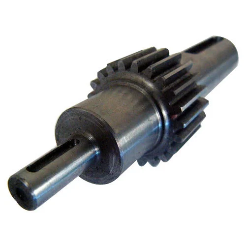
Gear shafts have distinct characteristics that differentiate them from other components in gear mechanisms. Here are some key differences between gear shafts and other components:
- Function:
Gear shafts serve as the mechanical linkages that connect and transmit rotational motion between gears. Their primary function is to transfer power and torque from one gear to another, enabling the desired mechanical output. Other components in gear mechanisms, such as gears themselves, may have different functions, such as meshing with other gears, providing different gear ratios, or changing the direction of motion.
- Structure and Design:
Gear shafts typically have a cylindrical or rod-like structure with a smooth surface. They are designed to provide support, alignment, and rotational movement for the connected gears. In contrast, other components, such as gears, may have complex tooth profiles, specific shapes, or specialized features to achieve their intended functions, such as transmitting motion, altering speed, or multiplying torque.
- Location and Mounting:
Gear shafts are often positioned centrally within gear mechanisms and are mounted on bearings or bushings. This central location allows them to connect with multiple gears and efficiently transmit power. Other components, such as gears, may be positioned at different locations within the mechanism, depending on their specific roles and interactions with other gears.
- Rotational Movement:
Gear shafts primarily rotate within the gear mechanism, transmitting the rotational motion from one gear to another. They are designed to withstand the torque and rotational forces applied during operation. In contrast, other components, such as gears, may have different types of movement or interactions, such as meshing with other gears, sliding, or engaging and disengaging with additional mechanisms or clutches.
- Size and Dimension:
Gear shafts can vary in size and dimension depending on the specific application and gear mechanism requirements. They need to be designed to handle the load, torque, and speed demands of the system. Other components, such as gears, may also come in various sizes, but their shape, tooth profiles, and dimensions are tailored to achieve specific gear ratios, rotational speeds, or torque multiplication.
- Material Selection:
Gear shafts are commonly made from strong and durable materials, such as steel or alloy metals, to withstand the forces and stresses encountered during operation. The material selection for gear shafts prioritizes strength, wear resistance, and fatigue resistance. Other components, such as gears, may have different material requirements based on their specific functions, such as hardness, friction properties, or heat dissipation.
In summary, gear shafts differ from other components in gear mechanisms in terms of their function, structure, location, movement, size, and material selection. Gear shafts primarily serve to transmit power and torque between gears, providing support, alignment, and rotational movement. Understanding these differences is crucial for designing and assembling efficient and reliable gear mechanisms.


editor by CX 2023-11-03
